Type “AK” Adjustable Disc Air-Friction Clutch & Brake Manual A-151-D
1. Click a link to view parts below or download a PDF Spec Sheet
2. Once you’ve found your part number and part name, request a parts quote
Questions? Contact Us
Jump to Assembly Parts and Manual Drawings
Click to enlarge
Download a PDF Spec Sheet
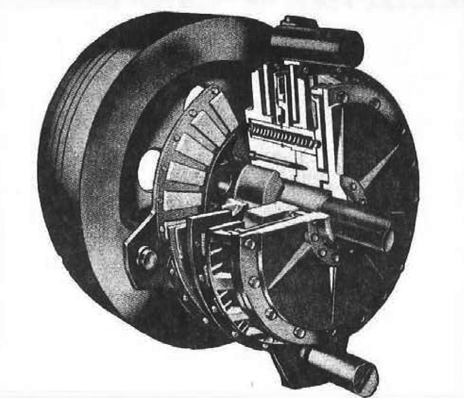
Bliss "AK" Clutch
The Bliss ”AK” clutch is a combination pneumatic friction clutch and spring-loaded disc brake. Compressed air is used to engage the clutch. When the air pressure is released, the springs set the brake.
The clutch has an adjustable feature to insure instant engagements and full energy transfer after normal wear has taken place on the linings.
Operation
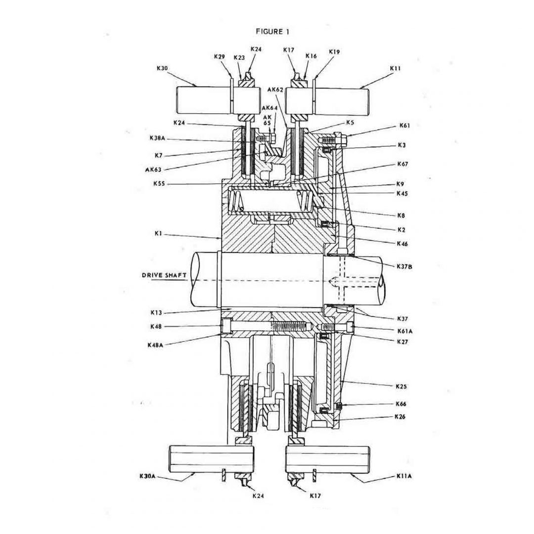
The single disc clutch consists of two friction discs. one for the clutch (K-24), and one for the brake (K-17). See Figure 1. Brake and clutch linings (K-5) and (K-7), respectively, are fastened on each side of these discs. (K-5) and (K-7) are furnished as assemblies. Other major parts consist of one driving disc (K-38A), eight driving pins (K-45}, two clutch friction disc pins (K-30), two brake friction disc pins (K-11), eight brake springs (K-8}, piston (K-9) with one large packing (K-3). one small packing (K-2), clutch body (K-1), air cylinder (K-46), clutch cylinder head (K-25), brake driving disc (AK-62), and the adjusting ring (AK-63).
The double disc clutch consists of three friction discs, two for the clutch (K-24), and one for the brake (K-17). See Figures 2 and 4. The double disc clutch is similar to the sing le disc except for the additional clutch driving disc (K-38), friction disc (K-24), and plate and block assemblies (K-7).
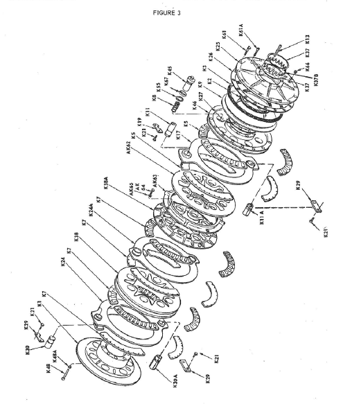
The double disc clutch and the double disc brake consists of two clutch friction discs (K-24) and two brake friction discs (K-17). See Figure 3. This model is similar to the double clutch, single brake except for the additional driving disc (K-38), friction disc (K-17). and plate and block assemblies (K-7).
The clutch friction disc revolves with the flywheel while the brake friction disc is stationary. The clutch friction disc is held to the flywheel by clutch friction disc pins (K-30 and K-11). The brake friction disc is held to the brake bracket by the brake friction disc pins (K-11 and K-30). Both clutch and brake friction discs float on their respective pins. The frict ion discs are guided on the pins by disc bushings (K-23 and K- 16).
NOTE: The clutch friction disc and the brake friction disc have one fixed end and one floating end. The floating end has flats on the pin and clearance in the friction d isc bushing for allowing expansion of the clutch due to heat.
The clutch and brake friction discs are separated by the “driving assembly” which consists of the clutch driving disc (K-38A}, the brake driving disc (AK-62,), and the adjusting ring (AK-63) with screws (AK -64). This assembly rotates with the driveshaft, the clutch body (K-1), and the air cylinder (K -46). The “driving assembly” is moved by air pressure to engage the clutch, and by spring pressure to set the brake.
To engage the clutch, compressed air is admitted to the air cylinder (K-46) through the driveshaft and the cylinder head (K-25). The air pressure moves the piston (K-9) which compresses springs (K -8) and moves the driving discs (K-38A) away from the brake disc toward the clutch disc. This grips the rotating friction disc (K-24) between the driving disc (K-38A} and the clutch body (K-1), thus creating the friction for starting the driveshaft. rotating and transferring the flywheel energy to the driveshaft. Air pressure must then be maintained in the line to the air cylinder (K-46) during the required operation of the press.
When air pressure is released, the brake springs move the driving disc away from the clutch disc and toward the brake disc. This grips the motion less brake disc, disengaging the clutch and creating the friction necessary to stop the crankshaft.
An air pressure failure will disengage the clutch and automatically set the brake . (Section 3. 5. 2. 11 of ANSl-811.1 1971).
Bliss Type "AK" Clutch
| Part # | Part Name |
|---|---|
| K1 | Clutch Body |
| K2 | Piston Packing - Small |
| K3 | Piston Packing - Large |
| K5 | Plate - Block Assembly - Brake |
| K7 | Plate - Block Assembly - Clutch |
| K8 | Brake Spring |
| K9 | Piston |
| K11 | Brake Friction Disc Pin (Fixed End) |
| K11A | Brake Friction Disc Pin (Floating End) |
| K13 | Clutch-Shaft Item |
| K16 | Brake Friction Disc Bushing |
| K17 | Brake Friction Disc Assembly |
| K19 | Friction Disc Pin Retainer |
| K21 | Friction Disc Pin Retainer Screw |
| K23 | Clutch Friction Disc Bushing |
| K24 | Clutch Friction Disc Assembly |
| K24A | Clutch Friction Disc Assembly |
| K25 | Cylinder Head |
| K26 | Cylinder Head Gasket (Large) |
| K27 | Cylinder Head Gasket (Small) |
| K29 | Friction Disc Pin Retainer |
| K30 | Clutch Friction Disc Pin (Fixed End) |
| K30A | Clutch Friction Disc Pin (Floating End) |
| K37 | “O” Ring |
| K37B | “O” Ring Spacer |
| K38 | Clutch Driving Disc |
| K38A | Clutch Driving Disc |
| K45 | Driving Pin |
| K46 | Air Cylinder |
| K48 | Clutch Body Screws |
| K48A | Washer |
| K55 | Driving Pin Snap Ring |
| K61 | Cylinder Head Screw - Outer |
| K61A | Cylinder Head Screw - Inner |
| AK62 | Brake Driving Disc |
| AK63 | Adjusting Ring |
| AK64 | Adjusting Ring Screw |
| AK65 | Lock Washer |
| K66 | Pipe Plug |
| K67 | Wear Ring |
Air service must be provided lo operate the clutch. A single air line inlet is usually provided on the press, to which the shop air line must be connected. Piping is arranged so that all compressed air passes through a common filter or separator. Branch lines leave the outle t side ol the lifter to the clutch and other air devices, when furnished. An air pressure regulator in each branch line maintains proper operating pressure for these devices. See Figure 3.
Recommended maximum operating air pressure is 70 P.S.I.
Actual requirement for each press is shown on an instruction plate attached to press frame (Figure A)
An air line lubricator is provided in the branch line to the clutch, and is installed between the clutch pressure regulator and clutch operating valve. The lubricator should be adjusted to a line mist on every clutch engagement. Use a high grade straight mineral lubricating oil with a viscosity of 145-165 SSU@ 100° F. SAE No. 1O.
An air tank is required in the clutch line to reduce the pressure drop at each clutch engagement.
The air line filter bowl must be drained regularly for effective performance. There is a “drain cock” at lower end of bowl for this purpose. Never permit moisture to fill bowl above baffle or up to filter element, otherwise, collected moisture and emulsion may be carried into the air line.
Note that the air tanks are provided with drain cocks to remove accumulated moisture.
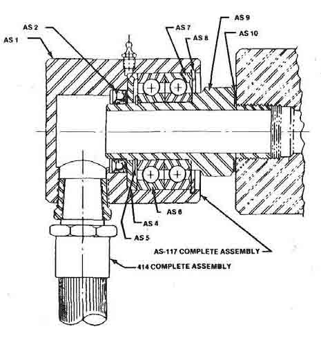
An air swivel and hose provide a flexible connection between the clutch operating valve and the drive shaft.

Click to enlarge
Parts List
| Part # | Part Name |
|---|---|
| K-SA | Brake Lining Plate Bolt and Nut |
| K-7A | Clutch Lining Plate Nut and Bolt |
| K-5 | Brake Lining – 1 Inner, 1 Outer |
| K-7 | Clutch Lining – 1 Inner, 1 Outer |
| K-23 | Clutch Friction Disc Bushing |
| K-16 | Brake Friction Disc Bushing |
| K-11 | Brake Friction Disc Pin |
| K-30 | Clutch Friction Disc Pin |
| K-24 | Clutch Friction Disc |
| K-17 | Brake Friction Disc |
Clutch and Brake Lining Replacement
CLUTCH LINING REPLACEMENT
The replacement of the clutch and brake linings can be made without disma ntling the clutch. The clutch friction block assemblies are made in quadrants requiring four per friction face or eight for each friction disc . See Figure 5.
The lining assemblies can be removed by, first, removing the bolts and nuts (K-7 A) and then withdrawing the friction lining assemblies. New lining assemblies can be installed by reversing this procedure.
BRAKE LINING REPLACEMENT
Figure 6 (left) –This illustration indicates the ease with which the clutch friction plates can be replaced. This is accomplished without disassembling the clutch and with a minimum of down time.
This is the same as mentioned above for the clutch except that air pressure must first be applied to release the brake disc. Be sure stroke is down when changing linings.
Adjustment for Lining Wear
The clutch can easily be adjusted to take up any clearance between the driving disc (K-38A) and linings (K-7) which may have resulted from lining wear. Correct adjustment will insure instant clutch engagement, full energy transfer from flywheel to driveshaft, and will minimize air consumption.
Adjustment should be made when the amount of clearance between the driving disc (K-38A) and linings (K-7) exceed 3/16 inch. First remove the four cap screws (AK-64) then lap driving disc (K·38A) until it is free from (AK-63) and tum adjusting ring (AK-63) until there is no clearance between clutch driving disc (K·38A) and linings (K-7). Then back off adjusting ring (AK-63) 1/2 to 3/4 turn. Turn back additional amount if necessary to line up cap screw holes and replace cap screws (AK-64).
IMPORTANT: These clutches must be adjusted regularly to prevent clutch slipping and creating excess heat.
General Assembly of Swivel and Hose
| Part # | Part Name |
|---|---|
| AS-1 | Swivel Housing |
| AS-2 | Packing Ring |
| AS-4 | Spacer Ring |
| AS-5 | Truarc Retainer |
| AS-6 | Bearing |
| AS-7 | Bearing |
| AS-8 | Truarc Retainer |
| AS-9 | Sleeve |
| AS-10 | Gasket |
| AS-117 | Air Swivel - Complete |
| 414 | Flexible Hose – Complete |


